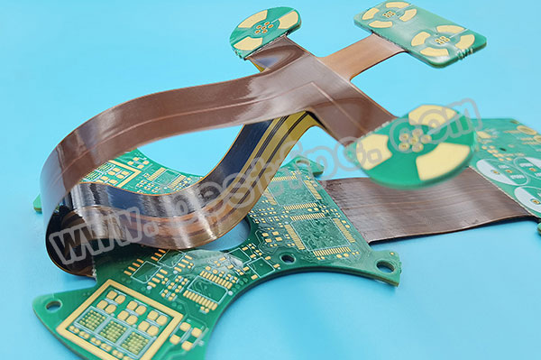
• Rigid-flex is the ideal solution for applications with multiple rigid PCBs having SMT components on both sides and requiring interconnects between the rigid PCBs.
• Before designing a rigid-flex circuit, make certain that it is truly what you need. If the circuit only has a few layers, stiffeners is a less expensive alternative to rigid-flex.
• It is most cost effective to build a rigid-flex with an even number of layers. All rigid portions of the circuit should have the same number and stack-up of layers.
• Observe aspect ratio (hole depth/hole diameter) limits.
• BEST TECH builds circuits up to 16 layers, but costs increase significantly above 10 layers.
• Expect a trim tolerance similar to that of a steel rule die from hole-to-border and border-to-border. Hole placement within a cluster of holes and from cluster-to-cluster will have a ±0.005" (0.13mm) tolerance within a single rigid area.
• Minimum inside corner radius of 0.031" (0.79mm) is standard, but smaller radius are available.
• Unbonded layers can increase flexibility in multi-layer flex circuits, but this option is more expensive. Specify unbonded layers only in areas of the circuit that will bend.
• BEST TECH can provide an epoxy fillet on stiffener edges that will bend or flex.
• For rigid-flex circuits, it is less expensive to have plated through-holes in the rigid portions only.
. BEST TECH can provide blind and buried vias in rigid-flex circuits
Fab Drawing: Rigid PCBs vs Flex PCBs
Rigid PCB Fab Drawings
• Board outline with dimensions
• Any other critical information that is not standard
• Drill map and drill legend for quality checks
• All board part data, or indication for manufacturer to use their standard
• Dimensions and locations of stiffener (reinforcements) and rigid areas
• Thicknesses of each portion of the board AND/OR materials to be used
• Application: Static or Dynamic
• Locations where board will flex and flex the most, if not obvious


 2022-11-08
 BEST
BEST


.png)
.png)
.png)
.png)

.png)

